

Parallelism is one of the geometric tolerances used to control how parallel a surface or feature is relative to a specified datum surface or datum axis. Proper control of parallelism helps improve assembly accuracy between components, resulting in better machine performance, smoother operation, and higher product reliability.
This article provides an easy-to-understand overview of parallelism, including its basic definition, importance, measurement methods, and how it differs from flatness, another type of geometric tolerance.
Contents
- What is parallelism?
- Parallelism symbol
- Concept of the parallelism tolerance zone
- Differences between parallelism and flatness
- Parallelism measurement methods
- Conclusion
What is parallelism?
Parallelism is one of the geometric tolerances that controls the degree to which a surface or line is parallel to a specified datum surface or datum line.
The JIS standard defines parallelism as follows:
JIS B 0621-1984: Definitions and indication of geometrical deviations
【Definition】Parallelism refers to the magnitude of deviation of a line feature or surface feature from a geometrically perfect line or plane that is parallel to a datum line or datum plane.
【Indication】Parallelism is represented by the magnitude of the zone occupied by a line feature or surface feature in the direction perpendicular to the datum line or datum plane. It is expressed as a parallelism value in millimeters (mm) or micrometers (μm).
In other words, it is a criterion used to ensure that a specified surface or line remains parallel to the datum within the prescribed tolerance range.
Parallelism symbol
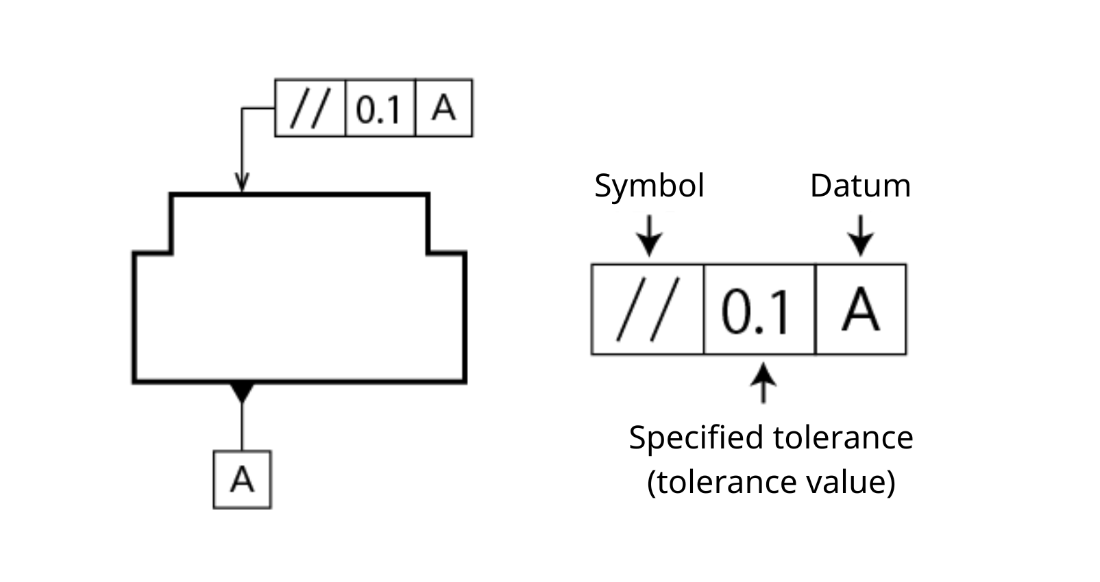
Parallelism requires a reference feature, such as a line or surface, to be defined as a datum. On engineering drawings, it is typically specified as shown below.
Concept of the parallelism tolerance zone
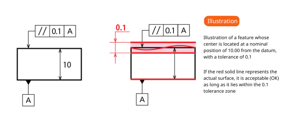
As shown in the figure below, if a parallelism tolerance of 0.1 is specified for the top surface of a part with a width of 10mm, the entire surface must lie within a tolerance zone of 0.1mm defined by two perfectly parallel planes located 10mm from Datum A (the reference surface).
As illustrated on the right, the requirement is considered satisfied if any waviness or variation of the controlled surface remains within the 0.1mm-wide tolerance zone that is parallel to Datum A and positioned 10mm away from it. In this case, the part is judged to meet the parallelism tolerance of 0.1.
Concept of parallelism for internal and external (holes and shafts)
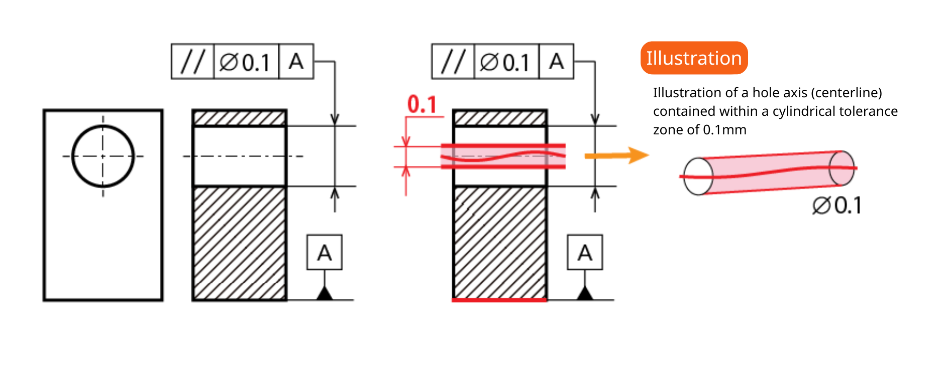
As shown in the figure below, if a parallelism tolerance of 0.1 is specified along the extension line of a hole dimension, the center axis of the hole must lie entirely within a cylindrical tolerance zone of Ø0.1mm that is parallel to Datum A.
As illustrated on the right, the requirement is satisfied as long as the axis (centerline) of the hole remains entirely within a cylindrical tolerance zone of Ø0.1mm.
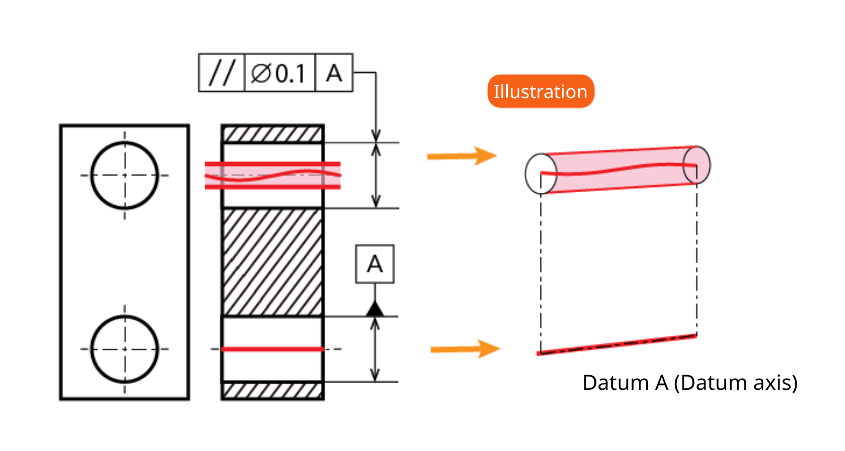
The same concept applies when a hole or shaft is designated as the datum feature.
Differences between parallelism and flatness
The following summarizes the differences between flatness and parallelism, two geometric tolerances that are often confused with each other.
| Symbol | Meaning | Datum required |
Parallelism | A tolerance that specifies how parallel a surface or line is relative to a reference surface or line (datum). | It is a related feature and requires a datum reference for machining and measurement. |
Flatness | A tolerance that specifies how flat a single surface is. | A single-feature tolerance that is applied directly to the surface, no datum is required. |
In summary, parallelism controls the relationship between two surfaces or lines, whereas flatness evaluates only the flatness of an individual surface.
For a detailed explanation of the geometric tolerance symbol「roundness」,please refer to the related article below.
What is roundness measurement? Difference between roundness and cylindricity
Parallelism measurement methods
The following are some of the most commonly used methods for measuring parallelism.
Caliper & micrometer
Parallelism can be evaluated by measuring the distance between the datum surface and the controlled surface at multiple locations using a caliper or micrometer. By measuring multiple locations on a workpiece using a caliper or micrometer, parallelism can be estimated from the variation in the measured values.
※However, this method provides only a simplified evaluation and is generally suitable for preliminary inspection.
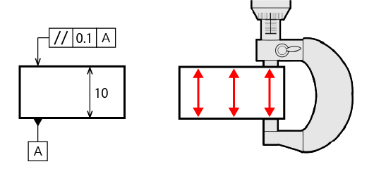
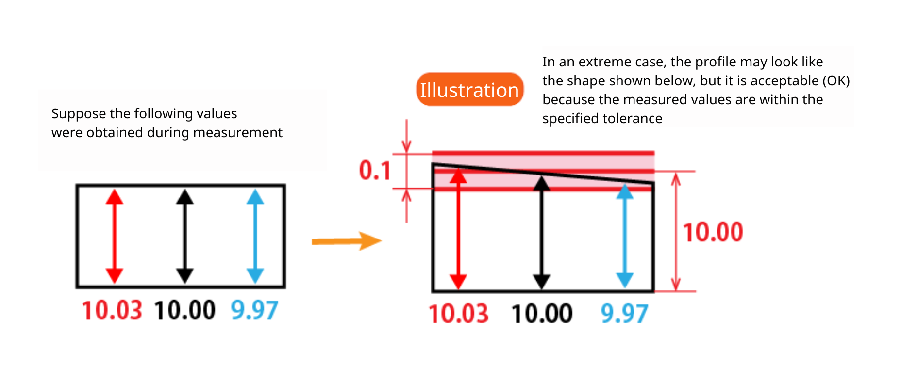
As shown in the figure below, suppose several measurements are taken across the 10mm width to verify a parallelism tolerance of 0.1. If the maximum measured value is 10.03mm and the minimum measured value is 9.97mm, the parallelism can be estimated as follows:
「Parallelism = Maximum value 10.03 − Minimum value 9.97 = 0.06」
Since the calculated value is within the specified tolerance of 0.1mm, the part is considered to satisfy the parallelism requirement of 0.1.
Height gauge & dial gauge
Measuring parallelism using a height gauge is to place the workpiece on a surface plate with the datum surface in contact with the plate. The height is then measured at multiple locations, and the difference between the measured values is used to evaluate the parallelism. When measuring the parallelism of a hole or shaft axis, the workpiece is similarly placed on the surface plate with the datum surface serving as the reference. The center height of the hole or shaft is measured at multiple locations, and the parallelism is determined from the difference between the maximum and minimum measured values.
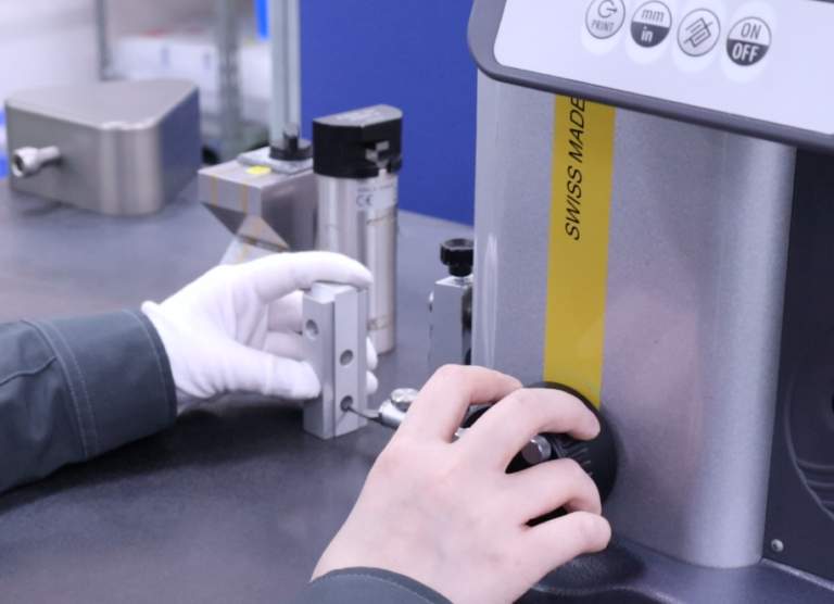
By replacing the height gauge probe with a suitable measuring attachment, the center height of a shaft can be measured, allowing the parallelism of the shaft axis to be evaluated. In addition, the measuring probe can be replaced with a dial gauge. By bringing the dial gauge into contact with the measurement surface and moving either the workpiece or the height gauge, the difference between the maximum and minimum readings can be used to determine the parallelism.
For more information about the digital height gauges available at Agency Assist Vietnam, please visit the page below.
Image-based dimensional measurement system
An image-based dimensional measurement system can be used to measure parallelism by capturing and analyzing an image of the workpiece.
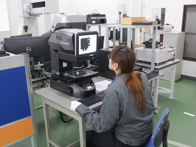
However, image-based measurement systems operate by projecting light onto the workpiece to create a silhouette, which is then captured and analyzed for measurement. Due to this characteristic, accurate measurement results may not be obtained if the workpiece geometry is unsuitable or if the focus is not adjusted correctly. Therefore, special care should be taken when using this type of measurement system.
Click here to view the introduction page for the image-based measurement systems used by Agency Assist Vietnam.
Coordinate measuring machine
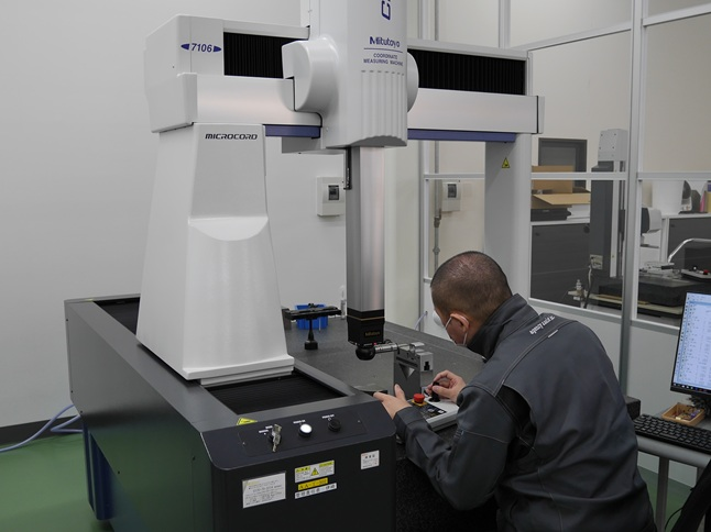
A coordinate measuring machine (CMM) can also be used to measure parallelism by creating geometric elements such as planes, cylinders, and lines from the measured coordinate data.
Conclusion
Parallelism is one of the most important geometric tolerances for ensuring product quality and performance. By controlling how parallel one surface or feature is relative to a datum surface or datum axis, manufacturers can improve assembly accuracy, machine performance, sealing capability, and overall product reliability.
At Agency Assist Vietnam, we support the manufacture of machined components from single-piece orders to mass production. Quality assurance and precision dimensional inspection are carried out at our Quality Control Center in Tay Ninh Province (Long An), where dedicated inspectors perform thorough inspections before delivery to ensure stable quality and reliable products for our customers.
Request a quotation here!