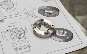


To ensure that a part is manufactured according to the intended design, design engineers specify「tolerances」on engineering drawings. A tolerance refers to「the allowable deviation from a specified reference value」. There are various types of tolerances, including dimensional tolerances and geometric tolerances.
In this article, we will focus on「roundness」- one of the geometric tolerances used in engineering drawings; and provide an easy-to-understand explanation of its characteristics, measurement methods, and the types of measuring instruments used. We will also discuss how roundness differs from「cylindricity」.
Contents
- What is roundness?
- Roundness symbol
- Roundness measurement method
- Features and considerations of roundness measuring instruments
- Conclusion
What is roundness?
Roundness is a geometric tolerance used to evaluate how closely the cross-section of a hole or shaft conforms to a perfect circle.
According to ISO 1101/JIS B 0621-1984, roundness is defined as follows:
Definition and indication of geometrical deviations:
【Definition】Roundness is the measure of how much a circular feature deviates from a true geometric circle. 【Indication】Roundness is defined as the radial difference between two concentric circles that enclose the actual circular profile with the minimum possible separation. It is expressed in millimeters (mm) or micrometers (μm) (For example: roundness_mm, roundness_μm).
Even holes and shafts that appear to be perfectly machined often contain slight distortions and waviness. By specifying a roundness tolerance, the shape of these circular features can be controlled.
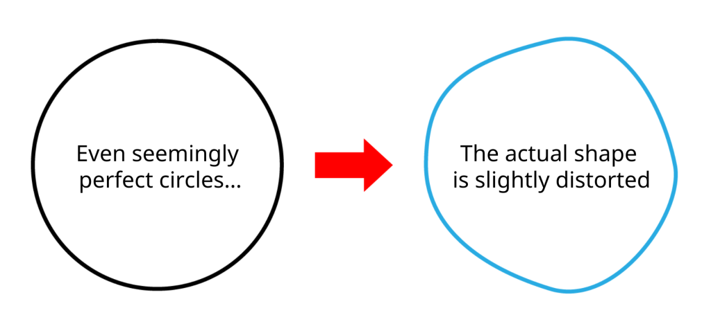
If the distortion is too large, the shaft may not fit properly into the hole, which can lead to abnormal noise, excessive wear, or even component failure. Therefore, the role of roundness tolerance is to control these deviations.
Achieving a perfectly round shape through machining is extremely difficult. Factors such as tool wear, machine condition, and machining parameters can cause various types of form deviations during the manufacturing process. Therefore, when measuring roundness, it is advisable to change the measurement position and perform measurements at two or more locations to obtain a more accurate evaluation.
Roundness symbol
In technical drawings, roundness is generally indicated as shown below.
As one of the geometric form tolerances, roundness does not require a datum reference, since roundness controls the form of a circular feature itself rather than its relationship to another feature.
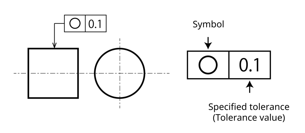
As shown in the figure above, if a roundness tolerance of 0.1 is specified for a shaft, it means that the magnitude of deviation of the shaft (such as distortion, waviness, or other form variations) must not exceed 0.1mm from a geometrically perfect circle.
→ For a more intuitive understanding, consider the following example:
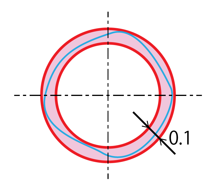
When a circular feature with a specified roundness tolerance is enclosed between two concentric perfect circles, it is considered to satisfy a roundness tolerance of 0.1 if the entire actual profile falls within the 0.1mm zone between those two circles.
Difference between roundness and cylindricity
The feature controlled by roundness is「a circular cross-section taken on a plane perpendicular to the axis of a cylinder」.When control of the entire cylindrical surface is required, the geometric tolerance of「cylindricity」is specified instead.
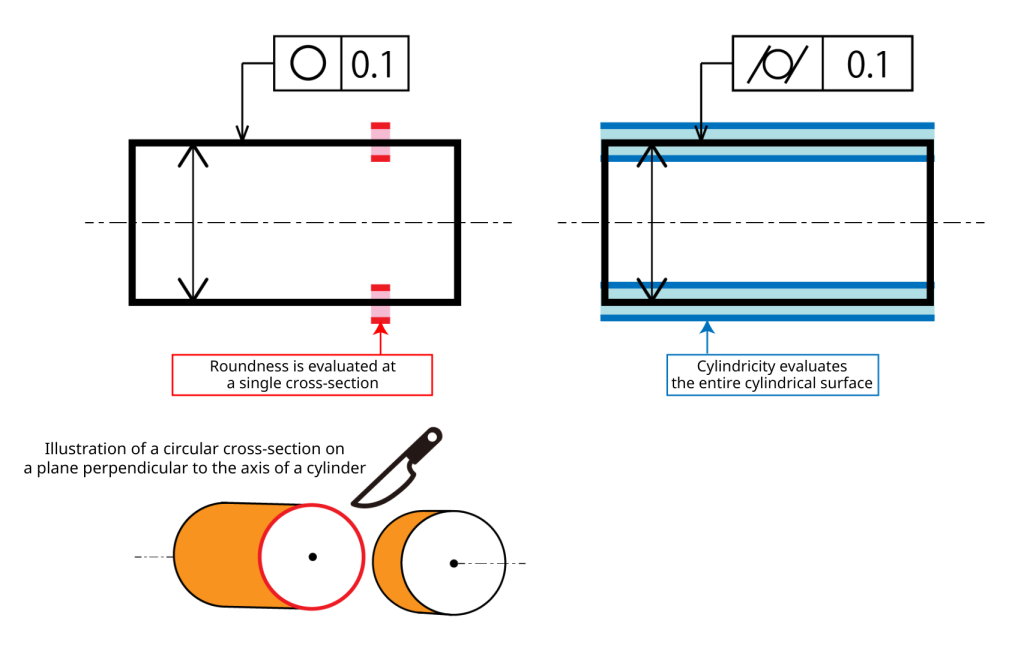
Cylindricity indicates how accurately a cylindrical feature maintains a true circular form over a specified length. It is commonly applied to rotating components such as shafts. If the cylindricity exceeds the specified tolerance, the component may no longer perform as intended.
Because cylindricity evaluates the entire cylindrical surface, a coordinate measuring machine (CMM) is commonly used. Furthermore, in practice, roundness and cylindricity are rarely specified at the same location on a drawing.
Roundness measurement method
Roundness measuring instrument
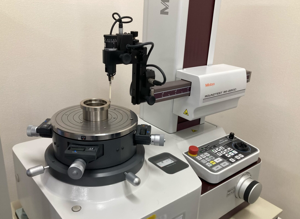
This method involves placing the workpiece on a rotary table and bringing a stylus (probe) into contact with the surface to measure minute deviations around the entire circumference.
This method enables the measurement of not only roundness and cylindricity, but also geometric tolerances such as coaxiality, parallelism, flatness, perpendicularity, circular runout, and total runout.
Caliper & micrometer
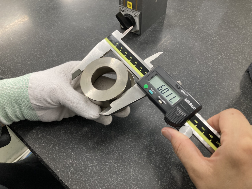
Roundness can also be estimated by measuring the diameter of a shaft at multiple positions using a caliper or micrometer. The roundness value is then obtained by dividing the difference between the maximum and minimum measured diameters by two.
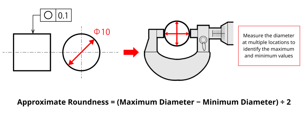
For example, suppose you want to verify the roundness tolerance of 0.1 shown above by measuring the Ø10mm section at several locations. If the maximum measured diameter is 10.03mm and the minimum measured diameter is 9.97mm, the roundness value can be estimated as follows:
Roundness = (Maximum diameter 10.03 – Minimum diameter 9.97) ÷ 2 = 0.03
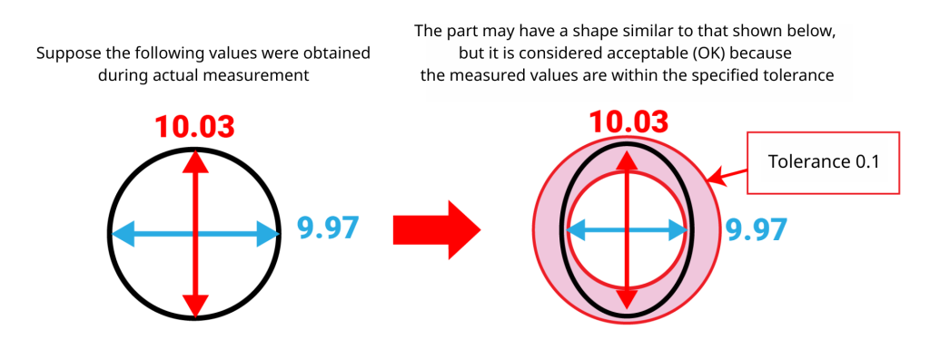
In an extreme example, the actual profile of the part could be considered elliptical, as shown in the figure above. However, because the calculated value remains within the specified tolerance of 0.1mm, the part is still considered to satisfy the roundness requirement of 0.1.
Height gauge & dial gauge
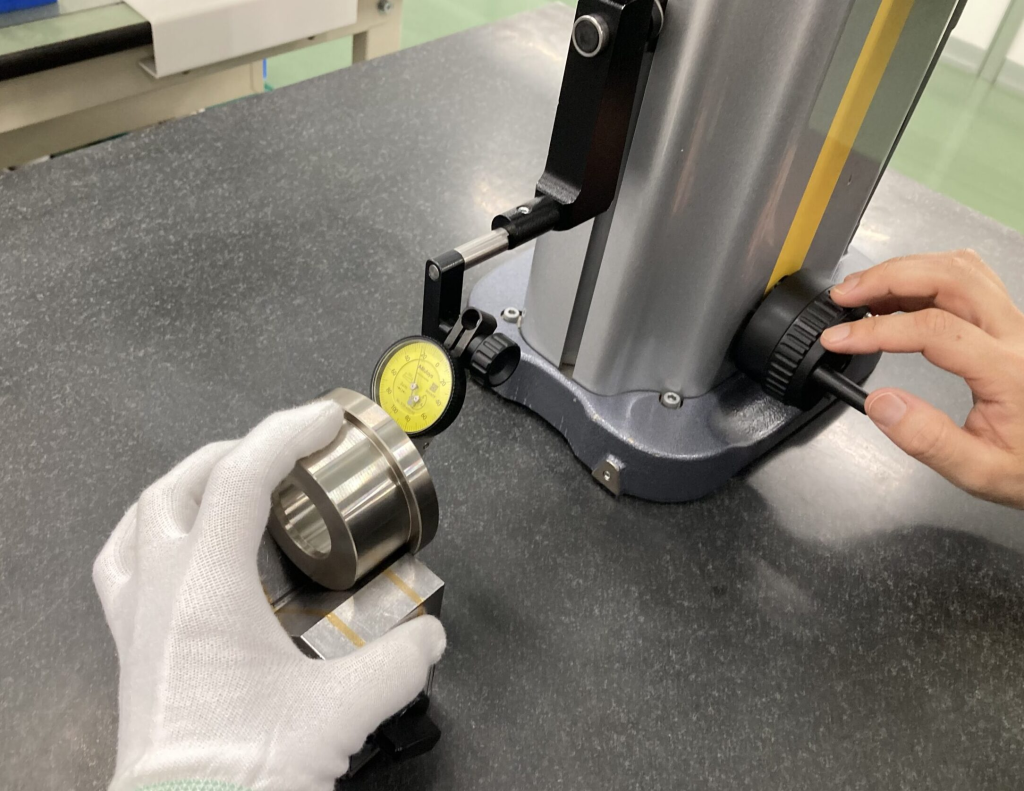
By replacing height gauge probe with a dial gauge and placing the workpiece on a V-block, the dial gauge probe can be brought into contact with the surface to be measured. The workpiece is then rotated one full revolution, and the roundness value is calculated by dividing the difference between the maximum and minimum readings by two.
Eccentricity gauge & dial gauge
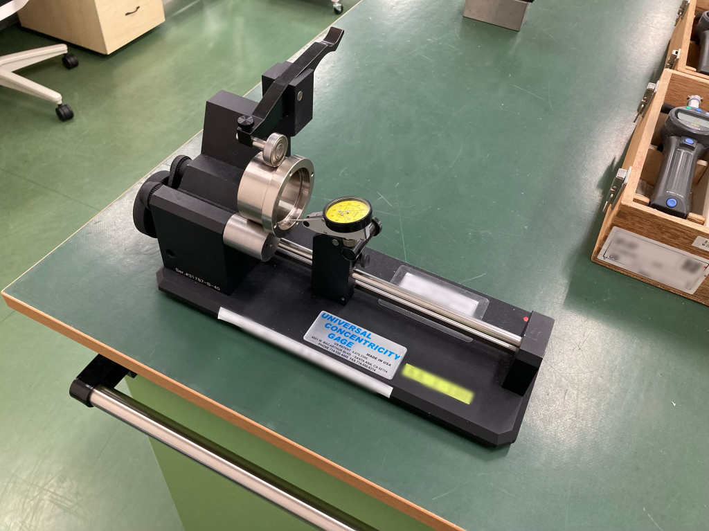
With the workpiece mounted on an eccentricity gauge, a dial gauge is brought into contact with the measurement surface. The roundness value is then estimated by rotating the workpiece one full revolution and dividing the difference between the maximum and minimum readings by two.
Three-point micrometer
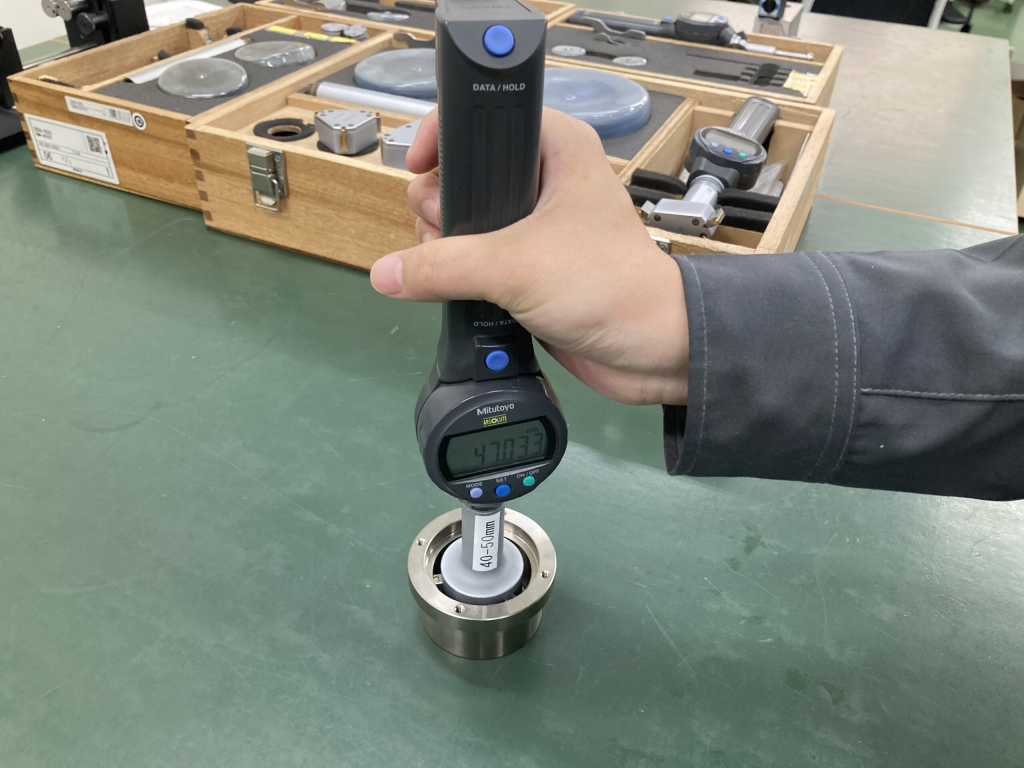
For measuring the roundness of an internal diameter, a three-point micrometer can be used to measure the bore at multiple locations. The roundness value can then be estimated from the difference between the maximum and minimum measured values.
Approximate Internal Roundness = Maximum measured value − Minimum measured value
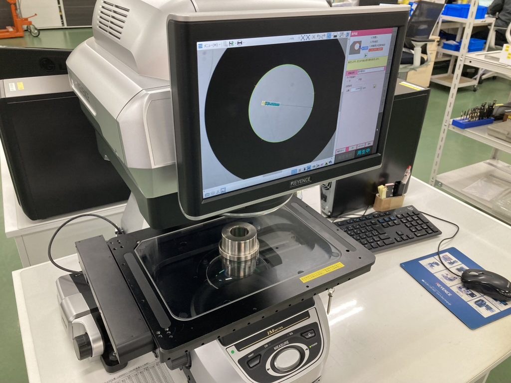
Other methods (Image-based dimensional measurement system and CMM)
Image-based dimensional measurement systems determine roundness by capturing and analyzing images of the workpiece, while CMMs evaluate roundness by collecting coordinate data through contact measurements taken at multiple points on the feature using a probe.
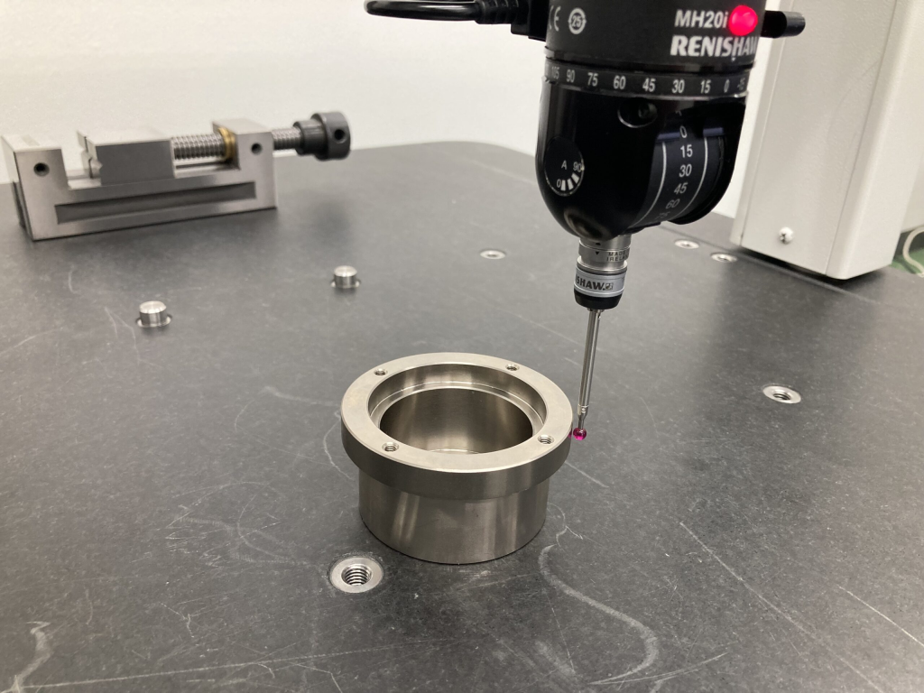
Agency Assist Vietnam’s Measurement and Inspection capabilities
Features and considerations of roundness measuring instruments
As mentioned earlier, no matter how carefully a part is machined to achieve a perfectly round shape, slight form deviations can still occur due to factors such as tool condition and machining parameters.
Depending on the measuring instrument used, it may be difficult to accurately evaluate roundness and detect subtle distortions. Therefore, it is important to understand the characteristics and limitations of each measuring instrument when assessing roundness.
Caliper & micrometer
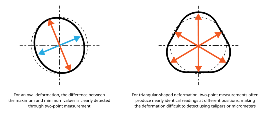
Since caliper and micrometer measure dimensions at only two contact points, they are more effective at detecting oval (elliptical) deformation than triangular-shaped deformation.
Three-point micrometer
As the name suggests, a three-point micrometer measures a feature at three contact points. This makes it effective at detecting triangular-shaped deformation (often described as an “onigiri”). However, oval-shaped deformation and localized irregularities may be difficult to identify, which can limit its effectiveness for certain roundness evaluations.
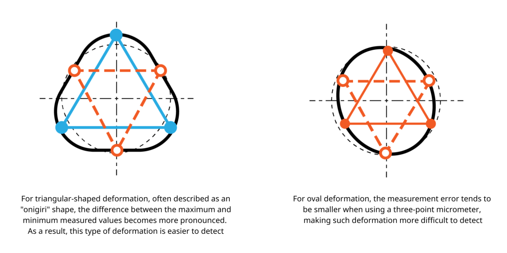
Image-based dimensional measurement system, roundness measuring instrument and coordinate measuring machine
Unlike calipers and micrometers, these instruments evaluate a circle using multiple measurement points. As a result, they can measure roundness accurately regardless of the type of form deviation present. However, the following considerations should be taken into account:
| Measuring instrument | Main considerations |
| Image-based dimensional measurement system | ・Only numerical results are displayed, making it difficult to identify the actual shape of the profile (This can be addressed by using additional shape analysis or visualization tools). ・For tall workpieces, overlapping shadows may cause the profile to be misinterpreted as an ellipse. |
| Roundness measuring instrument | ・Workpieces that cannot be securely fixtured may not be measurable. ・Improper measurement settings may result in probe-to-workpiece collisions. |
| Coordinate measuring machine | ・A small number of measurement points may fail to detect certain distortions, so an adequate number of points should be collected. ・Incorrect settings during automatic or scanning measurement may result in probe-to-workpiece collisions. |
Understanding the characteristics and limitations of each measuring instrument is essential for obtaining reliable measurement results. If the numerical results seem unusual, confirming them with a different measurement method can help ensure reliable and accurate measurement results.
Conclusion
If both the hole and the shaft have an oval shape, the shaft may be inserted into the hole, but it may not be able to rotate smoothly. Therefore, when evaluating holes and shafts, it is important to consider not only the outside diameter or inside diameter, but also the roundness of the feature.
Various methods are available for measuring roundness. To obtain accurate and reliable results, the measurement method should be selected based on the workpiece shape while taking the characteristics of each measuring instrument into consideration.
At Agency Assist Vietnam, we support the manufacture of machined components from single-piece orders to mass production. Quality assurance and precision dimensional inspection are carried out at our Quality Control Center in Tay Ninh Province (Long An), where dedicated inspectors perform thorough inspections before delivery to ensure stable quality and reliable products for our customers.
Request a quotation here!